Most of the time, oxygen sensor (O2) heater codes don’t present diagnostic challenges because we read the code, install a new oxygen sensor and we’re good to go. In other cases, O2 heater code diagnostics can challenge the intellect, especially when the same code is intermittently stored after a new sensor has been installed. I’ve been down that lonesome road of not knowing why, so bear with me while I explain.
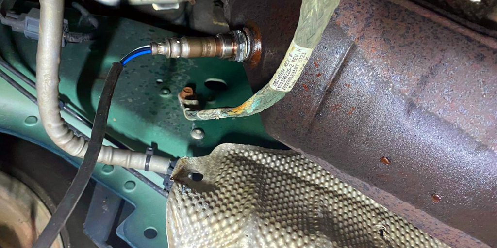
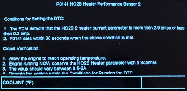
Since it displays a full range of scan tool data, I’m going to use a well maintained 2004 Chevrolet Tahoe with the 5.3L VIN Z engine to illustrate heater circuit diagnostics. This older-generation model is equipped with two 4-wire zirconia upstream and two 4-wire zirconia oxygen sensors downstream of the catalytic converters. The vehicle set a code P0141, indicating that the downstream bank 1, sensor 2 (B1S2) sensor wasn’t drawing enough amperage to satisfy the oxygen sensor test monitor (see Photo 1).
NARROW-RANGE OXYGEN SENSORS
A single-wire, narrow-range “zirconia” O2 sensor can generate a return signal ranging from 100 millivolts (mV) to 900 mV. A voltage value of 450mV or “center” indicates a chemically perfect 14.7:1 or “stoichiometric” air/fuel ratio that occurs only when all the atmospheric oxygen and hydrocarbon fuel is burned inside the combustion chamber.
Once the zirconia thimble reaches approximately 725° F, the sensor begins producing a voltage signal. At that point, the ECM gains fuel control and begins pulsing the fuel injectors from rich to lean, roughly between 200 mV to 800 mV.
This switching pattern creates the familiar saw-tooth zirconia sensor waveform (see Photo 2). For the past several decades, closed-loop and fuel control are achieved as soon as the upstream oxygen sensors become active. Once closed loop is achieved, the O2 sensor helps trim fuel delivery to produce stoichiometric at idle and part-throttle conditions
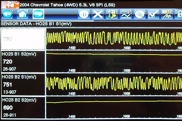
Currently, narrow-range sensors are used to monitor catalytic converter efficiency. When the catalyst on our 2004 Tahoe is cold, the downstream return signal mirrors the switching activity of the upstream zirconia sensor. As the catalyst warms and becomes active, the downstream sensor produces a linear, straight-line voltage return signal, usually in the range of 700 mV, which indicates the catalyst is operating at least 95% of maximum efficiency.
BROAD-RANGE SENSORS
Broad-range, air/fuel ratio (AFR) sensors can monitor air/fuel ratios from as rich as 12:1 to as lean as 22:1. Unlike the saw-tooth pattern of the narrow-range sensor, the AFR sensor generates a linear or straight-line voltage return signal that varies according to the air/fuel ratio. In general, many AFRs and scan tools display a voltage return signal between 3.0 and 3.5 volts, indicating stoichiometric.
Upstream Exhaust Temps – A majority of vehicles use the more efficient broad-range AFR sensor to monitor feed gases exiting from the engine exhaust into the catalytic converter. Broad-range air/fuel ratio (AFR) sensors require at least a 1,200° F operating temperature to generate a steady return signal to the ECM. Since exhaust gas temperatures reach 1,200° F only at wide-open throttle (WOT), the AFR sensor requires a very efficient heating system to maintain operating temperature. For this reason, the AFR’s heater circuit is commanded on most of the time.
Downstream Exhaust Temps – Downstream catalytic converter temperatures can vary widely due to differences in ambient air temperature, engine speed, engine load and the condition of the catalyst itself. Consequently, down-stream O2 sensors might use different operating strategies to operate their downstream heater circuits. During the 1990s, for example, many Fords delayed activating the downstream heaters because the moisture from the cold catalyst would crack the hot zirconia thimble during engine warm-up.
HEATER CIRCUITS
Wiring and fuse box diagrams are your best friend when diagnosing intermittent or erratic heater code problems. I’d also recommend using a professional volt/ohm meter, a 60-amp inductive probe, a “fuse loop” to go with the low-amp probe, and an inexpensive kitchen timer that measures minutes and seconds to help locate some of the more elusive O2 sensor heater problems.
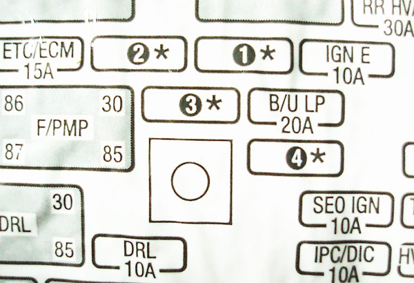
The first step in diagnosing heater circuits on our 2004 Tahoe is to verify power at the under-hood fuse box (see Photo 3). Sensor heaters can be powered by fusible links or, more commonly, by one or two mini-fuses. If no voltage is present at the “hot” side of the fuse, use your wiring diagram to locate the key-on voltage source, which would be the Ignition 1 fuse on our Tahoe.
P0141 HEATER CODE
The Tahoe’s powertrain control module (PCM) verifies the heater circuit by measuring heater resistance during a cold start. That resistance will vary according to intake air temperature (IAT). The PCM then commands the heater circuit “on” by grounding the heater circuit at the PCM for a duration of 50 milliseconds at one-second intervals. The PCM then measures amperage flow through the heater circuit. In this case no amperage flow is indicated through the bank 1, sensor 2 (B1/S2) heater, so P0141 sets in the diagnostic memory, indicating a heater circuit failure on B1/S2.
P0141 Enable Criteria – The conditions for running the P0141 heater monitor include:
- the engine coolant temperature (ECT) is greater than 122° F.
- 10-18 volts are present at Ignition 1 fuse,
- fuel alcohol content is less than 90%,
- The PCM has commanded the heater circuit on and
- the MAF sensor indicates at least 3-40 grams per second (gps), engine speed is between 500-3,000 rpm, and an engine run time of more than 120 seconds is indicated.
Heater Resistance Test – The PCM measures heater resistance when: 1) the ignition is off for more than 10 hours, and 2) the ECT indicates between -22° F. and + 113° F. at engine start-up.
Heater Amperage Test – If the PCM detects more than 1.375 amps or less than 0.25 amps flowing through the heater circuit for at least 10 seconds, P0141 is set in the diagnostic memory. In this case, the B1S2 sensor heater was open-circuit and the B2S2 sensor had 5.5 ohms of resistance at 60° F.
A Common Sensor “Failure” – An exhaust leak can cause upstream and downstream oxygen sensors to appear inactive on the scan tool. As a quick test, block the exhaust with a shop rag and engine running. Observing your scan tool data, if the voltage return signals of the upstream or downstream sensors return to normal, an exhaust leak is present.
CHRYSLER-SPECIFIC ISSUES
Off-specification heaters can cause O/2 heater codes on some Chrysler vehicles. I once had a 1998 Jeep Cherokee Sport produce an intermittent P0138 code, indicating that the B1S2 return signal remained over 1.5 volts for over 3 seconds.
The PCM supplies a 5.0-volt bias voltage to the B1S2 sensor circuit. The B1S2 acts as a resistor when it’s cold. When B1S2 warms up, the 5.0 bias voltage pulls down. If B1S2 fails to warm up fast enough, the bias exceeds the 0.2-volt maximum anticipated by the PCM and P0138 is set.
I discovered that P0138 was set only when sub-freezing temperatures were present during an initial start-up. Inserting a fuse loop into #23 fuse, I measured the amperage flowing through the heater circuit and, using my kitchen timer, I could see the elapsed time for the B1S2 sensor to reach operating temperature.
If the Jeep idled too long during warm-up, P0138 would also set and the malfunction indicator light (MIL) would illuminate. If the Jeep was driven away at speed, B1S2 heated very quickly and the MIL would remain off. A new OEM B1S2 oxygen sensor cured the intermittent MIL problem.