Throttle by wire was once a mystery. It was first used on a German V12 to synchronize the two banks of cylinders with two throttle bodies. Over the past 20 years, throttle-by-wire has become the standard technology on all gasoline engines. So, what can go wrong? A lot!
On older throttle cable systems, the carburetor or fuel injection system reacted to the throttle angle. When the driver smashed the throttle to the floor, the air flowing through the venturis would cause more fuel to be sucked into the engine. On older fuel injection systems, the injector open time would increase. The opening of the throttle was never synchronized with the fuel. As a result, the engine might experience rich or lean conditions when the throttle is opened or closed. These throttle “tip-in” conditions can increase emissions, and the driver might notice the lack of power.
Throttle-by-wire systems proactively manage the air and fuel going into the combustion chamber. The throttle angle might be delayed to allow the fuel to catch up. During events like increased loads on the alternator caused by electric power steering, the throttle angle will keep the engine speed constant.
The other advantage to throttle-by-wire is the ability to manage power from the engine during ABS, ESC and traction corrections. Older throttle cable systems would cut spark to the cylinders and induce a misfire to reduce power. New systems reduce throttle during a correction to reduce power. But, this can add a new wrinkle to diagnostics and communication on the vehicle.
Throttle-By-Wire Anatomy
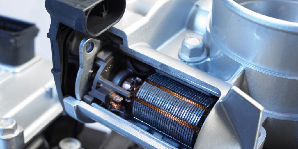
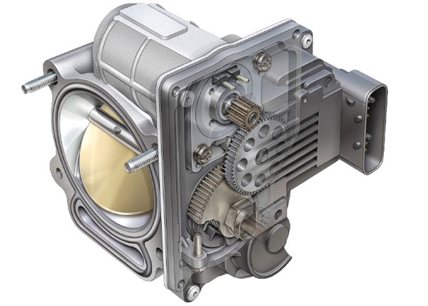
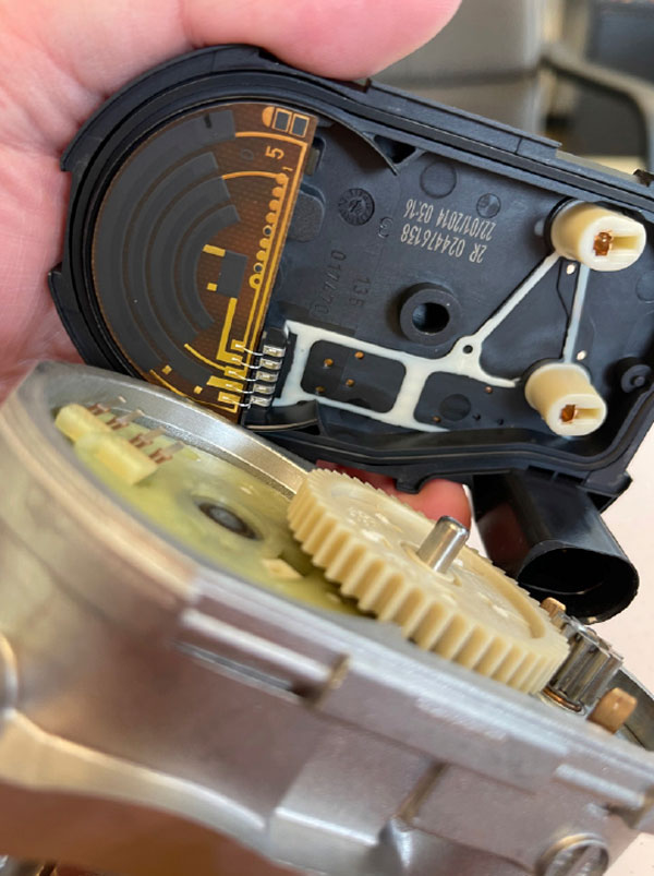
All throttle-by-wire throttle systems have the same basic parts. First is the throttle body that controls the air entering the engine. The plate is connected to gears that provide gear reduction to a connected electric motor. On the other side of the shaft of the throttle body are two or more position sensors. The sensors will vary resistance depending on the angle of the throttle.
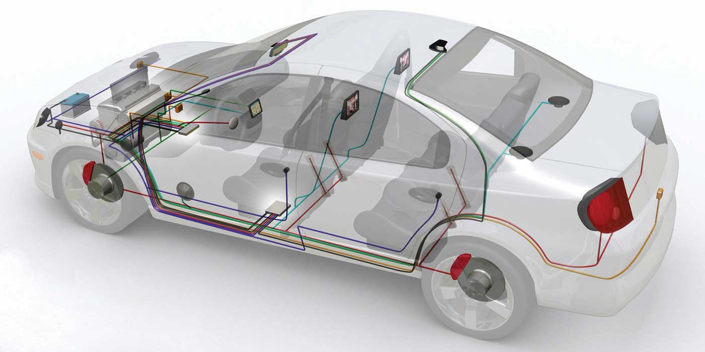
Why two throttle angle sensors? The two sensors double-check each other. One sensor will increase resistance as the throttle angle is increased, one sensor will reduce resistance as the throttle angle is reduced. In the connector, there will be pins for two five-volt reference voltage and signal wires for each throttle position sensor. On some systems, the signal voltages will add up to five volts or the reference voltage. These are typically wired directly to the ECM. The ECM shares the calculated throttle angle with the ABS, transmission and other modules.
The motor that moves the throttle plate uses a pulse-width-modulated voltage. The 12-volt signal is switched on and off in exact intervals to control the position of the throttle plate. Some systems are able to change the polarity of the voltage for better control.
Throttle Triage
When dealing with throttle-by-wire issues, the most likely customer complaint you will hear is the vehicle will go into a limp mode that limits engine speed. Other complaints might be that ABS or stability control lights are illuminated. It is rare for a throttle-by-wire code to completely disable the throttle body and prevent it from idling.
Most codes will be saved and might have freeze-frame data. Most active codes will clear with a single key cycle. When retrieving codes, check for codes in other modules for loss of communication. This could indicate that the ECM has lost communications with other modules on the network, which will usually be the high-speed CAN bus. These issues need to be resolved before trying to troubleshoot a throttle-by-wire problem.
As for codes, most of the codes for throttle-by-wire are for the throttle position sensors. Codes P0120-P0124 are for sensor A. Codes P0220-P0224 are for sensor B. Codes 0225-P0229 are for sensor C. The codes in the three sets cover circuit malfunctions like high or low inputs. These codes indicate an issue with the throttle-by-wire unit or the wiring.
One of the most common codes is P2119 for Throttle Actuator Control Throttle Body Range/Performance. This code is typically set when the commanded or desired throttle position does not match the actual throttle position. P2119 is a plausibility code indicating data does not match between the input and output.
P2119 can be caused by a variety of mechanical and electrical problems. For example, on some vehicles, if a throttle angle change does not alter the signal from the mass airflow sensor or manifold air pressure sensor, P2119 can be set.
When looking at the datastream, there are several data PIDs to look for. The first two PIDs are the actual and commanded throttle angle. On most vehicles, these two data PIDs should match. The second set of data PIDs to look for are the reference voltages for sensors A and B. The reference voltage for the two sensors should be the same. Last, look at the signal voltages of sensors A and B. For most vehicles, when you add up the two signal voltages they should equal the reference voltage.
The throttle angle controls air entering the engine for idle and during cruise. The angle can vary depending on the condition of the engine. There are also conditions where you might not see rapid changes in the data PID for the throttle angle.
The throttle-by-wire system can also compensate for long-term conditions like small vacuum leaks and carbon buildup at the throttle body and intake valves. It does this by increasing the angle of the throttle plate. As carbon builds up or other conditions that change idle quality change, it can increase or decrease the angle of the plate.
RELEARN AND ADAPT
If a throttle-by-wire unit is replaced or cleaned and installed, the vehicle will have to relearn the values of the pedal and plate. Some vehicles do this automatically every time they are started. However, some vehicles require a special key, pedal sequence and/or test drive cycle.
Most modern vehicles relearn throttle angle and idle settings using a scan tool. This can be faster than allowing the system to relearn on its own and can prevent giving a customer a car back with the check engine light on. This reset should be performed on some vehicles if the battery is replaced.
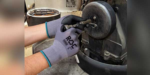
CLEANING A THROTTLE BODY
Carbon deposits around the throttle plate are caused by crankcase vapors and combustion gases inside the intake manifold. Since most throttle bodies are heated to prevent icing, it makes a perfect environment for carbon buildup.
The next time you want to see how effective a throttle cleaning service is, use your scan tool and record the throttle angle or idle compensation PIDs at idle before and after the cleaning.