The grandfather of all waveforms is the secondary ignition waveform. Technicians have been looking at this waveform since the 1960s to determine the health of ignition system components. The secret to being able to capture and analyze secondary ignition waveforms is understanding what is happening in the coil and at the spark plug and how the scope measures and graphs the voltages and ignition event.
How is it measured?
Measuring the voltage of the secondary ignition directly is not an option, these high voltages will damage any scope or meter. To capture a secondary ignition waveform requires a capacitive probe. This type of probe can be either the traditional clamp over an ignition wire or a “paddle” that makes contact with the surface of the coil or wire.
The primary and secondary windings of the coil transform the energy from low-voltage/high-current energy to high-voltage/low current energy. Eventual this energy is discharged through the spark plug electrodes. The flow of energy changes the magnetic field in the wires or coil. This change in the field is picked up in millivolts by the clamp or paddle probe.
Most clamp or paddle probes have a conversion factor of 10:1. This means that 1 volt at the scope input equals 1,000 volts or one kilovolt (kV) in the secondary. Some clamps or probes may have an attenuator (10:1 or 20:1), make sure you read the instructions to set up your scope. Some scopes will convert the voltage scale to kV when the ignition probe is selected.
A capacitive probe should have a ground clamp as part of the test leads. This creates an easier path to ground for the thousands of volts generated by the coil. If the probe or clamp is not grounded, the voltage could damage the internal circuitry of the scope. Most scopes have a limit around 200 volts, and most ignition systems can generate more than a 4,000 volts.
What are the settings for the scope?
When you are trying to set up a scope to measure secondary ignition waveforms, the goal is to capture the ignition event from when power is applied to the coil to the point where the coil oscillates with the remaining energy. This can happen in 6-10 milliseconds. One millisecond per division is typically the optimal time base depending on the size of your screen and the type of ignition system.
A healthy coil and ignition system generates 3-4 kV at idle. As load and engine speed increase, the kV spike will increase. Some systems can generate more than 50 kV under certain conditions. You may need to adjust your voltage scales to capture the total output of the spike.
On most scopes, the trigger should be set to auto or single with an increasing slope. With some scopes, you will be able to use an auto or repeat trigger setting to stabilize the waveform. There are also options to offset or delay the trigger to fit the entire event on one screen.
Try to become familiar with setting up secondary ignition triggers with your setup before you are under the diagnostic labor gun. If you have a more advanced scope, you can select the secondary ignition probe in the probes menu, the presets will load the correct voltage range, time base, and type of trigger. Some scopes will also convert the voltage scale to kV. Depending on the type of ignition system, you may have to fine tune the trigger and voltage scale fully capture the waveform on a single screen.
What are the sections of the waveform?
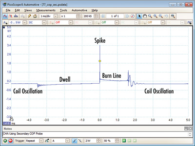
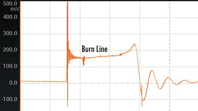
A secondary ignition waveform can be broken down into three parts. First, the area of the waveform that shows dwell where the secondary of the coil is saturated with energy from the primary. Second, the spike shows the initial start of the spark between the electrodes. Third, the burn time is the area of the wave where the spark is burning between the electrodes and eventually stops.
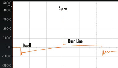
Saturation/Dwell
The first part of the waveform is the charging of the secondary coil by the primary. This is where the energy of the primary saturates the secondary coil. There will be an initial sharp voltage drop followed by a sine wave that is a coil oscillation. This oscillation is the module turning on power to the coil. As the secondary becomes saturated, the line will slowly go up in a steady ramp. The critical shape of this part of the waveform should be smooth ramp upwards. It can change due to demands on the engine.
Spike
The spike is where the coil discharges and the spark jumps from one electrode to the other. This spike changes depending on the resistance between the electrodes. The resistance depends on what is going on inside the combustion chamber.
Imagine the air and fuel inside the combustion chamber as ohm resistors between the spark plug electrodes. If you increase the distance between the electrodes, you are increasing the amount of air between the electrodes and the value of the resistor between them. As cylinder pressure increase and fuel mixture changes, the amount of energy required to fire the also plugs increases. This is why the spike should increase in height if you snap the throttle.
If the spark line does not increase when the throttle is snapped or is lower when compared to the other coils, it is a sign the spark might be escaping to areas other than the spark plug electrodes. This could be caused by a shorted connector or boot with an air gap. The spike stays the same height because the conditions around the short do not change with engine RPM.
There are not specifications for the spike, but it should look like a single line on most scopes. After the spike has dropped, you should see small decreasing oscillations.
The key with the spike is to compare it to the other coils on the vehicle. If one spike goes higher than the rest, it is a sign of two things. First, the resistance in the combustion chamber could be different then the rest of the cylinders or the spark plug could be worn. If the spike is significantly lower than the rest of the cylinders, it is a sign that the resistance is lower in the plug or cylinder. In some case a clogged or dead fuel injector can cause a lower spike when the throttle is snapped.
The Burn
The burn line is the burn time of the spark between the electrodes. It will typically last 2 to 3 milliseconds. The “perfect” burn line should be a constant decreasing slope at idle. The line can have small changes and can appear jagged on some scopes. This has been theorized as changes in the gases and turbulence in the cylinder.
At the end of the burn line is the coil oscillations. This is the energy left over in the coil. It should have three or four smooth humps. If it has a spike and a short burn time, it is a sign there is an open in the wire or boot preventing the energy from going to the plug.
Interpreting Secondary Ignition Wave Forms
On modern coil over plug (COP), wasted spark or coil near plug systems you are using the secondary waveform as a comparative tool. You can compare a waveform to a known good pattern from a database or you can compare the waveform to the other cylinders. Waveforms will differ from engine to engine.
On some systems you may see a 1- to 2-kV hump after the spike, or you might not see a coil oscillation when the primary coil is energized. This could be normal for some systems. The secret is to compare the waveform with the other cylinders.