By: Gary Goms, courtesy of ImportCar magazine
By the dawn of the Industrial Age, the gasoline internal combustion engine had replaced steam power as the driving force behind America’s great economic expansion. In that day, a cranking, no-start condition could easily be diagnosed by testing the available spark at the spark plug. If there was no spark, we touched a test light to the coil negative terminal to determine if the distributor contact points were switching the coil on/off (see Photo 1). If the test light blinked, the primary circuit was switching as designed, so we replaced the coil. A pretty simple diagnosis, right?
But today’s ignition systems pose an entirely different set of problems because the crankshaft sensors, camshaft sensors, ignition coils, spark plug wires and spark plugs used in modern systems are often buried under intake plenums, drive belts and rotating accessories. So, when we can’t access the secondary circuit, which consists of the spark plugs, wires and ignition coils, we can diagnose the secondary ignition system through the “back door” by testing the primary circuit.
Modern Switching Systems
The primary circuit switching function begins with the crankshaft position sensor (CKP) reporting the crankshaft position in rotational degrees, relative to top dead center (TDC) of each cylinder to the engine control module (ECM). Modern engines with solid-state primary ignitions also mount a camshaft position (CMP) sensor at a camshaft drive sprocket to indicate number-one cylinder arriving at compression stroke. The ECM uses this input data to correctly time the spark advance curve according to engine operating conditions.
The sole exception to the above statement is the waste-spark system in which each coil of a “coil-pack” assembly simultaneously fires two companion cylinders, one at TDC compression stroke and the other at TDC exhaust stroke. Since either companion cylinder is at TDC, the waste-spark ignition doesn’t require a camshaft position sensor to determine TDC compression stroke. In any case, a scan tool can be used to verify switching function (see Photo 2).
CKP Codes
The absence of a CKP trouble code is relatively meaningless when diagnosing cranking, no-start failures. In most cases, a CKP code is a “two-trip” code, which means that the CKP must fail two consecutive times before the check engine light will illuminate. Depending upon the vehicle, the initial CKP failure will be recorded as a pending code. After a key-off cycle, the second CKP failure should illuminate the check engine light and store as a history code.
Scope Testing the CKP
A lab scope can be used to observe the quality of the CKP signal. A two-wire magnetic reluctor sensor should produce a waveform that switches smoothly from positive to negative voltage at approximately a 3-volt amplitude during cranking.
A three-wire Hall Effect sensor should produce a crisp square-wave pattern that pulls to zero volts during cranking. If the Hall sensor signal tends to “float,” or if the square-wave pattern is a corrupted, it can’t be read by the ECM. The exception to this rule is the magneto-resistive sensor that doesn’t pull to zero volts, but should display a crisp square-wave signal.
A Primary Voltage Test
Dwell angle is the number of camshaft degrees that current is flowing through the ignition primary circuit. Positive duty cycle or “on-time” is another measure of the same phenomenon. Since the dwell angle or duty cycle on modern ignitions can be very low at cranking and idle speeds, using a test light probably won’t indicate a switching function.
One quick method of testing switching function is to use a digital volt/ohm meter (DVOM) for comparing voltages at coil B+ and coil negative terminals. In general, this test works better on single or waste-spark coils than with coil-on-plug designs.
At key-on, engine off, both terminals should show battery voltage. Although the exact voltage differential depends upon the type of system, the coil negative voltage should decrease in proportion to the amperage flowing through the primary winding during cranking.
If B+ and coil negative voltages are equal during cranking, the ECM isn’t switching the primary circuit. Your conclusion should be that the ECM coil driver or driver circuit isn’t switching the primary circuit.
A Word About Testing Coils
In theory, ignition coils can be diagnosed by comparing the resistances of the primary and secondary circuits to specification at room temperature. In reality, the resistance test is a static test that means little unless the test value is well out of specification.
In the real world, most coils will fail only under dynamic conditions of heat and load, both of which can be very difficult to duplicate. It’s far more cost-effective to replace the suspect coil, than to spend hours trying to duplicate a heat and load condition. Your choice, but I’ve had too many “saved” coils come back to haunt me.
Low-Amp Probes
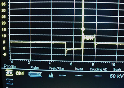
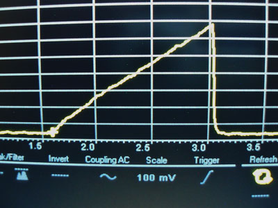
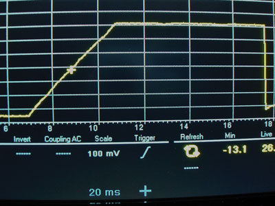
That said, another way to diagnose some primary systems is to connect a low-amperage inductive current probe or “amp clamp” to a lab scope. The probe is then attached to the voltage source powering the coil. In most cases, the coil B+ wire can be accessed at a common voltage source in the wiring harness. In other cases, the coil’s current flow can be measured at the fuse box or at the coil B- terminal in the ECM connector (see Photos 3 and 4).
COP Testing
The coil-on-plug (COP) system, which mounts an ignition coil on each spark plug, is now the current standard for modern engines. A failed coil-on-plug is relatively easy to identify since a coil failure usually results in a P0301 to P0312 misfire code as indicated by a scan tool.
Two-wire COP connectors contain a B+ voltage source and a coil negative circuit to the ECM coil driver. Four-wire coil connectors, as used in some Toyota applications, contain a B+ voltage source, a B- battery/chassis ground, an IGT (ignition timing) and an IGF (ignition fail) circuit as well. The coil dwell and timing are controlled by the ECM through the IGT coil terminal. The 5-volt IGF circuit reports coil activity to the ECM. Both the IGT and the IGF activity can be verified with a lab scope. As with two-wire coils, four-wire coils can also be diagnosed by searching for misfire codes with a scan tool.
Ignition Monitors
Space doesn’t allow, but many manufacturers incorporate a number of circuit-specific trouble codes into their COP ignition systems. In this case, your enhanced scan tool is your best friend. If that data isn’t available, use your lab scope to its best advantage.
When testing primary ignition, be aware that many digital lab scopes won’t tolerate the high voltage “kicks” (about 250kV to 400 kV) present in the primary circuit. When measuring the primary waveform with any lab scope, it’s best to protect your lab scope by using an attenuated 10:1 lead designed for direct primary circuit testing.
Sidebar:
It’s All in the Technique
Let’s diagnose a cranking, no-spark complaint on an engine with the spark plugs covered by the intake plenum. Let’s also bury the ignition coil inside the distributor cap, as on some older Mitsubishi V-6 engines. And, since voltage is king in any electrical diagnosis, let’s make sure the battery is in good condition and fully charged.
Here’s how I begin a basic cranking, no-start primary ignition diagnosis:
- Use the least intrusive methods for diagnosing cranking, no-start failures.
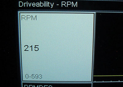
- If the engine tachometer shows a cranking speed of around 200-300 rpm, the CKP is reporting crankshaft position to the ECM.
- If the engine tachometer shows zero cranking rpm, it’s time to connect an enhanced scan tool.
- If the scan data indicates zero cranking rpm, or if a dedicated data line indicates no CKP activity, the crankshaft position sensor isn’t reporting crank position to the ECM.
- If available, primary circuit trouble codes will quickly identify a primary circuit problem
- If available, a bi-directional test for ignition can be used to verify coil and coil driver operation.
- If the scan tool bidirectional can’t activate the ignition primary circuit, the ignition likely has a voltage source problem caused by a burned fuse or a faulty ignition switch.
- Use a wiring schematic to locate fuses and relays that might power the ignition system.
- Use the wiring schematic to develop a diagnostic strategy for locating wiring splices and connector problems.
- Since all ignition systems share basic operating principles, it’s easy to develop a diagnostic strategy that will quickly locate any primary ignition failure.