By Glen Beanard
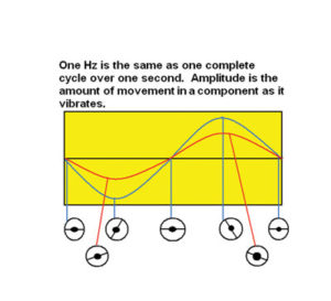
Vibrations are expressed in “first order,” “second order” and so on. The “order” of the vibration is simply how many “bumps” it makes per revolution. Imagine a tire with one bubble in the tread. Every time that tire rotates, one “bump” can be felt as that one bubble slaps the road’s surface. That is a first order vibration. If there are two bubbles in a tire located in two different places, then two bumps can be felt per each revolution of that tire. That is a second order vibration. Three bubbles would make a third order vibration, and so on.
It’s important to remember that if a measurement and calculation is made that doesn’t exactly fit any component in the first order, it will be necessary to start looking at vibrations in the second order and on.
Engines have a preset order to their vibrations. That order is equal to half of the number of cylinders that an engine has. That’s because per every one revolution of an engine, half of its cylinders fire, producing a “bump” per firing. A four-cylinder engine has a second order vibration; a six-cylinder engine has a third order vibration, and so on.
Classifying the Vibration
During the test drive, the vibration must be classified into whether it is vehicle-speed related or engine-speed related.
To determine if a vibration is vehicle- or engine-speed related, the easiest thing to do is slip the transmission into neutral and let the vehicle coast when the vibration is most noticeable. If the vibration continues, then the vibration is vehicle-speed related. Likewise, if the vibration subsides, the vibration is engine-speed related.
It’s imperative to know whether the vibration is vehicle- or engine-speed related so you know what parts to suspect.
Vibration Measuring Tools
When it comes to vibration measuring tools, you certainly get what you pay for. The cheapest tool is called a sirometer. A sirometer is nothing more than a coil of wire inside of a two-piece plastic housing. Dialing the top half of the sirometer lengthens and shortens the wire. The vibrations make the wire vibrate when the length is set just right for a particular frequency. Then, the user reads a numeric scale on the housing of the sirometer to see where a little pointer stopped at to get the frequency. Although it’s surprisingly accurate, it’s not made for automotive use where someone would be measuring frequencies while driving down the road. It is actually used by small-engine technicians to determine engine rpm of lawn mower engines.
The tools of choice are electronic vibration analyzers (which were used in this article). The simplest versions provide Hz, rpm (Hz times 60) and amplitude. The most sophisticated of these tools go so far as to actually name the suspect part(s). When using the simpler versions of a vibration analyzer, it is also wise to use a special vibration analysis software on your PC that performs the calculations for you and points directly to the suspect part(s).
With any vibration measuring tool, always make your measurements under the conditions when the vibration is most noticeable. Then, always note the vehicle speed and engine rpm that correspond with the exact moment the vibration frequency is recorded. Plus, for best results, make the measurements in places on the vehicle where the vibration can be felt the best, like the seat tracks, steering column and floor pan. Taking measurements directly on the source of the vibration can result in inaccurate readings.
Calculating Natural Frequencies and Real-World Testing
A vibration analyzer provides a frequency and amplitude of the component that is vibrating. Everything has a preset frequency that it emits when it vibrates. The frequency measured is a fingerprint of the component that is causing the problem.
Let’s start with the tires. To calculate the frequency of a tire from scratch, first calculate the tire’s diameter. This can be done with a size chart. For example, a 255/70R16 would show a total diameter of 30”.
To find the rpm of the tire, you then need to calculate the circumference (try using an online tire size calculator or use π x diameter). This will give a circumference of 94.4”. Then divide the 63,360 (inches in a mile) by 94.4”. The revolutions per mile is 692. Now we can determine the frequency, or revolutions per second, by dividing by 60 for an answer of 11.5 Hz. When using this formula, it will provide a Hz reading for the vibrating tire at around 60 mph.
The tire given here will produce a first order vibration with a 11 Hz to 12 Hz reading if it were the source of the highway speed vibration. If there are two bubbles on the tire, then it will produce a second order vibration reading between 22 Hz and 24 Hz.
Now that we have the tire frequency, we can calculate the driveshaft vibration for a rear-wheel-drive vehicle. First, obtain the rear axle ratio. Multiply the ratio by the first order tire frequency. The ratio will be 1:3.08. So, 3.08 x 11.5 Hz gives us 35.42 Hz. Therefore, at highway speed, an out-of-balance driveshaft on this vehicle will produce a reading between 35 Hz and 36 Hz at about 60 mph. If the driveshaft were bent in a way that produced a second order vibration, we would read between 70 Hz and 72 Hz. Remember though, this is for RWD driveshafts and not FWD half shafts.
A simple imbalance condition will always produce only a first order vibration. In order to have a second order or more vibration, something has to be bent or spinning off center.
The Real World
Alright, let’s see what happens when classroom theory meets the real world. Let’s start simple and work our way up.
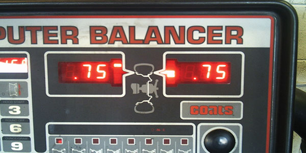
The first vehicle is a 2003 Ford Taurus. It has P215/60/R16 tires. At 60 mph, a vibration can be felt. The vibration is vehicle-speed related. It is felt in the seat and the steering wheel, so I’m thinking it’s a common tire balance problem. The EVA shows 12 Hz and 0.03 G at the vehicle speed of 60 mph (vehicle speed tracked on a scan tool).
The calculated frequency of these tires, and everything spinning at that same speed as the tires, is 13 Hz. The rotors, tires, hubs and the half shafts are suspected. One of the tires was found to be 5 oz. out of balance (see Photo 1).
The balance fixed the problem, but what if it didn’t? What if the tires were in perfect balance and not out of round? Then at least we would know for sure that we are looking for something that can create a 12 Hz first order vibration at 60 mph. We also know for sure that it has to be something that is turning at the same speed as the tires since those items are the only thing turning that slow. This helps narrow our search.
What if we measured 36 Hz? What could make a 36 Hz vehicle-speed related vibration that might be similar to tires? Thirty-six Hz doesn’t match anything in the first order or the second order for that car, but it does match the tripod joint on a CV axle when looked at in the third order. The next vehicle is a 2001 Silverado 2×4. This truck has a vibration around 40 mph and 1,500 rpm that is hardly noticeable, but is there. The vibration analyzer has picked up a vibration of 36 Hz measured at the center console.
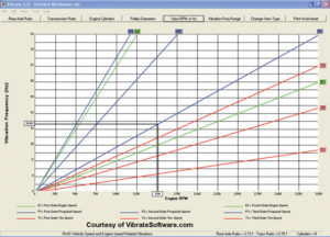
The rear differential ratio is 1:3.73 and the tires are 255/70R16. Everything is found earlier in this article for you to calculate the source of the vibration. However, let’s try some special software that does the calculations for us. After plugging the rear differential specs into the software, and the engine rpm at which it occurred, we get an answer of first order driveshaft vibration (see Figure 1). The vibration is labeled as a first order propeller shaft vibration. And what do you know, the software and manual calculations are correct.
Hose clamps were added to the driveshaft to generate this vibration.