Gary Goms – Technical Contributor
The key to diagnosing many cranking, no-start and stalling problems found on the late-model import is to understand how the crankshaft and camshaft position sensors function and what their mechanical relationship is to each other. During the past 30 years, ignition control systems have evolved from distributor-type, to distributorless, to coil-on-plug ignition systems. Similarly, fuel injection systems have evolved from carbureted, to throttle body, to “banked” multiport, to sequential multiport systems. Quite obviously, it’s more important than ever to understand how the crankshaft and camshaft sensors function in each of these systems.
Going back to the basics, the Otto cycle engine requires two revolutions to complete one combustion cycle. The first revolution of the combustion cycle is composed of the intake and compression strokes. The second revolution is composed of the power and exhaust strokes. The purpose of the crankshaft (CKP) and camshaft position (CMP) sensors is to determine whether the crankshaft is on the first or second revolution of the combustion cycle, and to also determine which stroke is occurring in each cylinder.
Modern Fuel Injection Systems
The function of the distributor on throttle-body injected engines is to determine when each cylinder reaches top dead center (TDC) on the compression stroke. When the cylinder reaches TDC, the distributor triggers the ignition coil to provide a spark to the compressed air/fuel mixture.
The issue of determining TDC compression stroke becomes more complex with multiport electronic fuel injection. Early multiport systems used a “banked” fuel injection system in which one-half of the fuel injectors were activated during each revolution of the engine. Obviously, banked injection systems were relatively inefficient and were discarded when engine computers became sophisticated enough to sequentially time the fuel injection cycle according to the firing order of the cylinders.
Some early banked systems use only a crankshaft position sensor to determine the TDC of each cylinder. In essence, the engine control module (ECM) on a four-cylinder engine might, for example, measure cranking speed while switching the fuel injection timing 180 degrees of crankshaft rotation until it “finds” the TDC compression stroke. In contrast, sequential injection systems must incorporate a camshaft position sensor to determine the TDC compression stroke of each cylinder during the first two crankshaft revolutions.
Modern Ignition Systems
Similarly, modern ignition systems have evolved from distributor to distributorless, to coil-on-plug systems. Early electronic import fuel injection systems incorporated the CMP and CKP sensors into the distributor, which allowed the distributor to time both the ignition and fuel injection events. With the advent of the distributorless ignition, in which a spark was supplied to pairs of cylinders rotating through the exhaust and compression strokes, the function of the CKP evolved into timing the ignition event, while the CMP evolved into timing the fuel injection event. That basic function has continued with the more recent coil-on-plug ignition systems.
In both the distributorless and COP ignition systems, the CKP is mounted at the crankshaft and the CMP at the camshaft. This configuration allows the CMP to monitor camshaft position and the CKP to monitor crankshaft speed, piston position, and the amount of crankshaft deflection or speed variation created during a cylinder misfire event.
Reluctor-Type CMP and CKP Sensors
In its most basic sense, the two-wire variable reluctor or “alternating current” sensor consists of a copper wire wound around a magnet. The magnet is placed close to a rotating reluctor made with projections or “teeth” that generate voltage in the sensor windings as the reluctor rotates past the sensor.
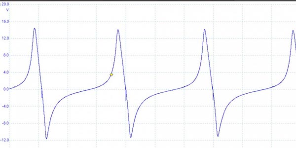
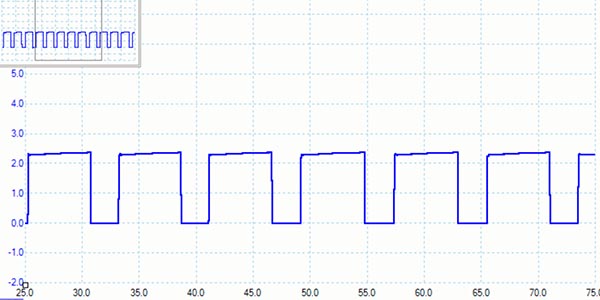
Shown in Photo 1 is a typical variable reluctor waveform generated by a distributor. As the reluctor speeds up, voltage increases from about 4V to about 6V. Notice that the sensor produces positive and negative voltage that crosses the “zero” line at an angle.
Hall Effect CMP and CKP Sensors
As seen in Photo 2, the Hall Effect sensor produces a square waveform. The square waveform more accurately times the spark because the voltage rise and decline is perpendicular rather than angled.
Unlike a two-wire variable reluctor sensor that generates its own voltage, a three-wire Hall Effect sensor requires an outside voltage source to generate a signal. In effect, the Hall Effect sensor is an electric switch that uses a shutter wheel rotating through an air gap to turn the current flowing through the sensor on and off. Because the voltage output is either positive or zero, the Hall Effect sensor is a more accurate sensor than the variable reluctor-type, which produces a varying voltage value.
When used in crankshaft position applications, both sensors indicate compression stroke on the number-one cylinder by a “signature” or “synch” waveform, which is created by changing the size or shape of a shutter or reluctor tooth. In applications that incorporate an external ignition module, the CKP signal indicates the position of the crankshaft to the PCM.
When servicing camshaft sensors, it’s important to differentiate between a camshaft position and camshaft timing sensor. Keep in mind that later-model imports like Nissan may also incorporate a camshaft timing sensor to monitor changes in camshaft timing. It’s important not to confuse the location and function of these two sensors during a sensor replacement.
Variable Reluctor Diagnosis
When Photo 1 is examined, it’s clear that the positive and negative voltage distribution and duration aren’t equal. Reluctor-type sensors are very sensitive to the strength of their magnets, the air gap between the sensor and reluctor, and the rotating speed of the reluctor itself. Because of these factors, a digital storage oscilloscope (DSO) will provide the most accurate measurement of variable reluctor voltage output.
Hall Effect Diagnosis
Because the Hall Effect sensor must produce a crisp, square waveform of the correct amplitude and the waveform switching “off” or pulling down to zero voltage, it’s necessary to use a lab scope to diagnose Hall Effect sensors. If the waveform doesn’t pull down to near-zero voltage, the PCM may not be able to “read” the signal from the Hall Effect sensor.
Regarding “unique” waveforms like those found in some Ford ignition systems, be aware that variations from the ideal square waveform might be unique to a specific manufacturer’s design rather than a failure in the sensor itself.
The lower waveform represents the Hall Effect signal generated by a distributor ignition, while the upper waveform is the return signal from the PCM.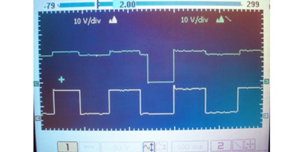
In Photo 3, the upper waveform is the timing signal generated by the PCM. The “synch” signal is the narrow pulse at the far right of the distributor pickup waveform. Notice also that the signal from the distributor is not pulling down to zero voltage. At the far right of the return signal, you’ll see that the PCM is no longer supplying a valid Hall Effect signal to the ignition module.
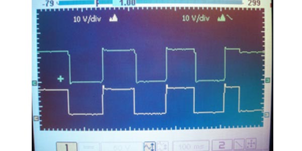
As seen in Photo 4, the return signal from the PCM is failing to pull down to zero voltage, which is causing a cranking, no-spark condition. Whether the “near-zero” voltage signals are significant depends upon the parameters built into the PCM’s software.
Continuing in Photo 4, the return signal from the PCM is completely failing to pull to zero voltage, which might be causing a cranking, no-spark condition in this Hall Effect distributor ignition system.
Intermittent Failure Diagnosis
Because they work in a hostile operating environment, CKP and CMP sensors are well known for developing intermittent failures. Whether a diagnostic trouble code (DTC) is stored depends upon the operating strategy and enabling criteria built into the PCM’s software. If a CKP fails during the cranking mode, the PCM may not “see” the failure simply because it has received no prior signal from the CKP. If, on the other hand, the CKP fails while the engine is running, the PCM may store an appropriate DTC.
Similarly, if the CMP fails while cranking, some operating strategies may adopt a default mode by changing the fuel injection timing until the injection cycle matches the compression stroke. In other applications, the CMP failure might cause an outright cranking, no-start condition. If the PCM “sees” a CKP signal without an accompanying CMP signal, it might then store a CMP failure code.